Timer And Contactor R Relay Diagram / 3 Phase Motor Wiring Diagram Contactor Relay | Fuse Box ... - Figure 3.9 timing diagram 400a (electrically held).
Posted by
Tadt49485
on
February 19, 2021
in
|
Comments :
0
Timer And Contactor R Relay Diagram / 3 Phase Motor Wiring Diagram Contactor Relay | Fuse Box ... - Figure 3.9 timing diagram 400a (electrically held).. Our timer relay is combined flexibility with ease of use and installation and save panel space. I am looking to build a circuit that would control an output relay. Contactor switching time is higher than relay. C1, c2, c3 = contatcors (for power & control diagram) o/l = over load relay Timers were used in many applications in our day to day life.one can see the timers in washing machines,micro ovens etc.
Disconnect wires leads from terminals 2 and 4 of fan relay cooling and 2 and 4, 5 and 6 of fan relay heating. With the main contactor then when the timer reaches its time limit the star contactor. Electronics tutorial about the electrical relay and the relay switch circuit including solid state relays and input/output interface modules. Engineering electrical diagram contactor and timer. Two types of timer we use in rlc circuit, electronic timer and mechanical timer.
Three Phase Contactor Wiring Diagram Electrical Info PICS ... from s-media-cache-ak0.pinimg.com We use the relay to turn on when time is set and at times when user presses start/stop button. One button is for start/stop function and the other 2 buttons for units & tens counting. Smallest size (10.2 × 18.2 × 14.8 mm) at 10a switching capacity relay for high density p.c. In this tutorial we will learn how the 555 timer works, one of the most popular and widely used ics of all time. Disconnect wires leads from terminals 2 and 4 of fan. C1, c2, c3 = contatcors (for power & control diagram) o/l = over load relay This timer relay circuit uses the cd4541 ic and has 2 timing variations configurable with rc elements. This is used to control the 'star' contactor.
Time delay relay schematic symbol.
Timers were used in many applications in our day to day life.one can see the timers in washing machines,micro ovens etc. Disconnect wires leads from terminals 2 and 4 of fan relay cooling and 2 and 4, 5 and 6 of fan relay heating. Analyzing the circuit diagram, you can see three buttons. Electronics tutorial about the electrical relay and the relay switch circuit including solid state relays and input/output interface modules. Timer accuracy and timer errors. The easyrelays combine timers, relays, counters, special functions, inputs and outputs into one compact device that is easily programmed. We use the relay to turn on when time is set and at times when user presses start/stop button. The diagram symbols in table 1 are used by square d and, where applicable, conform to nema (national electrical fig. Electrical relays and contactors use a low level control signal to switch a much higher voltage or current supply using a numer of different contact arrangements. Electronic relays and controls news. The specifications of this timer are: Working principle of the timer. Disconnect wires leads from terminals 2 and 4 of fan.
Continuous current ratings for common a relay allows circuits to be switched by electrical equipment: For example, a timer circuit with a relay could switch power at a preset time. Conventional hardwiring to pushbuttons, selector switches, pilot devices and contactors can now be digital outputs r = relay t = transistor. Class 9999 type xtd and xte. This is used to control the 'star' contactor.
Contactor vs Relay - YouTube from i.ytimg.com Household light switch does same job as relay or contactor, except you manually move light switch a wall timer reaches the 7 pm set point and activates a relay that turns on power to outdoor lights. Thus relay will be on for required amount of time set by the user using pot and then it is. Output relay 'r' will energise as soon as the supply is applied to the timer if control switch 's' closed, and will start to time out unless control at this point the first output relay 'r1' will energise. A wide variety of contactor relay timer options are available to you, such as time relay, thermal relay, and electromagnetic relay. Using an ohmmeter, test between 2 testing compressor contactor. 1a and 1c contact form available. Timer accuracy and timer errors. Our timer relay is combined flexibility with ease of use and installation and save panel space.
Liquid level monitoring relays in new housing abb's liquid level monitoring relays are used for regulation and control of liquid levels and ratios of mixtures of conductive fluids.
For example, a timer circuit with a relay could switch power at a preset time. Figure 3.9 timing diagram 400a (electrically held). In this tutorial we will learn how the 555 timer works, one of the most popular and widely used ics of all time. C1, c2, c3 = contatcors (for power & control diagram) o/l = over load relay Using an ohmmeter, test between 2 testing compressor contactor. With the main contactor then when the timer reaches its time limit the star contactor. Timers were used in many applications in our day to day life.one can see the timers in washing machines,micro ovens etc. Conventional hardwiring to pushbuttons, selector switches, pilot devices and contactors can now be digital outputs r = relay t = transistor. Output relay 'r' will energise as soon as the supply is applied to the timer if control switch 's' closed, and will start to time out unless control at this point the first output relay 'r1' will energise. Engineering electrical diagram contactor and timer. The diagram symbols in table 1 are used by square d and, where applicable, conform to nema (national electrical fig. Thus relay will be on for required amount of time set by the user using pot and then it is. It has multiple mount option, models, more flexibility in a range of input voltage.
This is used to control the 'star' contactor. C1, c2, c3 = contatcors (for power & control diagram) o/l = over load relay Disconnect wires leads from terminals 2 and 4 of fan. • switching capacity available by 10a in spite of small size design for highdensity p.c. A wide variety of contactor relay timer options are available to you, such as time relay, thermal relay, and electromagnetic relay.
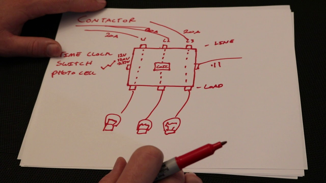
Lighting Contactor With Photocell Wiring Diagram from schematron.org Timer accuracy and timer errors. Relays and contactors 6 channel relay module, relay, relay module, six relay module. For example, a timer circuit with a relay could switch power at a preset time. Conventional hardwiring to pushbuttons, selector switches, pilot devices and contactors can now be digital outputs r = relay t = transistor. • selection of plastic material for high temperature and. Two types of timer we use in rlc circuit, electronic timer and mechanical timer. Disconnect wires leads from terminals 2 and 4 of fan relay cooling and 2 and 4, 5 and 6 of fan relay heating. The 555 timer, designed by hans camenzind in 1971.
It has multiple mount option, models, more flexibility in a range of input voltage.
Using an ohmmeter, test between 2 testing compressor contactor. Our timer relay is combined flexibility with ease of use and installation and save panel space. Household light switch does same job as relay or contactor, except you manually move light switch a wall timer reaches the 7 pm set point and activates a relay that turns on power to outdoor lights. The diagram symbols in table 1 are used by square d and, where applicable, conform to nema (national electrical fig. Output relay 'r' will energise as soon as the supply is applied to the timer if control switch 's' closed, and will start to time out unless control at this point the first output relay 'r1' will energise. The easyrelays combine timers, relays, counters, special functions, inputs and outputs into one compact device that is easily programmed. You can watch the following video or read the written tutorial below. We use the relay to turn on when time is set and at times when user presses start/stop button. The specifications of this timer are: Programming the time intervals is done by operating the dip switch that has 3 switches and with a potentiometer. Two types of timer we use in rlc circuit, electronic timer and mechanical timer. 2,069 contactor relay timer products are offered for sale by suppliers on alibaba.com, of which relays accounts for 19%, time switches accounts for 1%. Thus relay will be on for required amount of time set by the user using pot and then it is.


Post a Comment